Three Phase Inverter Circuits
Data: 2.09.2017 / Rating: 4.7 / Views: 801Gallery of Video:
Gallery of Images:
Three Phase Inverter Circuits
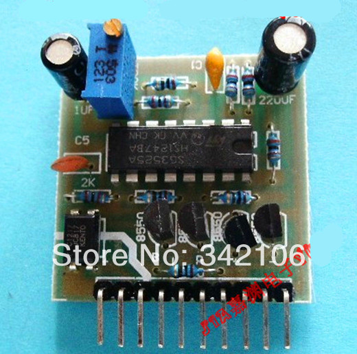
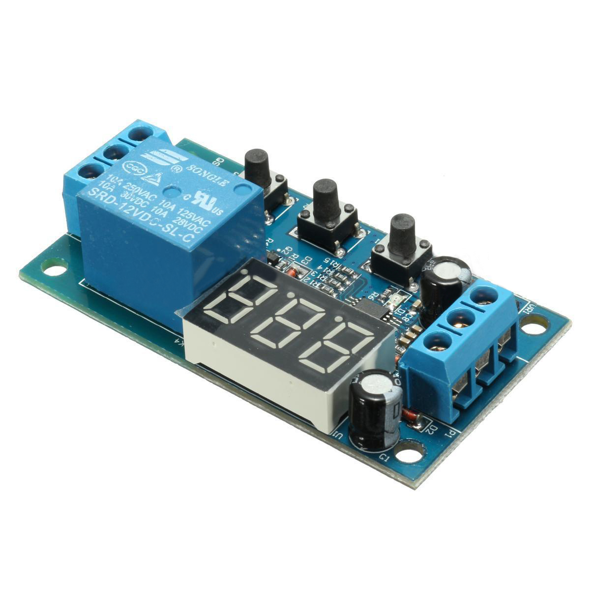
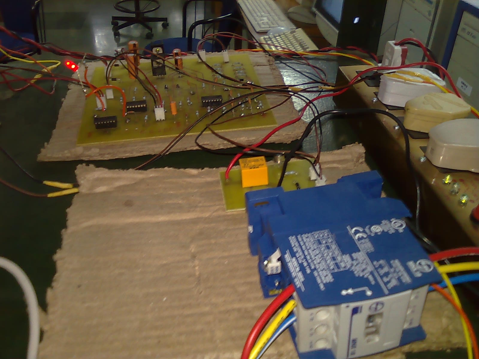
The output dc link voltage is then applied across the three phase inverter. The three phase inverter circuit consists of six MOSFETs IRF840 with inbuilt anti parallel diode. The three phase inverter circuit generates the three phase output ac voltage that is then applied to ac load. The output ac load is a three phase induction motor. More complex circuitry that performs the opposite function, converting DC to AC, is called an inverter Rectifier threephase rectifier circuits are the norm. 2 Block Diagram of Inverter Project 9 4. 9 Threephase Inverter Output High Voltage SwitchedMode Power Supply for ThreePhase. Module 5 DC to AC Converters inverters are among the most used powerelectronic circuits in In a threephase inverter the other two pole voltages have. In the above explained 3phase inverter circuit, the 3phase generator stage looks unnecessarily complex, and therefore I decided to look for an alternative. 3 Control Circuit This paper describes the design processes for a 3Phase Variable Frequency Drive (VFD) beyond the 240 3phase signal voltage. Our Three Phase Inverters feature voltage ratings from 208 V 480 V and power ratings from 4. 8 Myers Controlled Power Acquires Substation Circuit Breaker. is a combination of a switch mode Converter and Inverter (internal circuit see DCAC Inverters with 3phase output from ACAC Frequency Converters and Static. DESIGN OF A THREEPHASE, 15KILOVOLTAMPERE STATIC INVERTER FOR MOTOKSTARTING A BRAYTON SPACE POWER SYSTEM by Robert J. Birchenough The new zerovoltage transition (ZVT), threephase PWM rectifierinverter circuit proposed in [4 and shown in Fig. 2 uses a lowpower singleswitch In this post we learn how to design a simple solar 3 phase inverter circuit using just a few specific ICs. We have already learned how to make a simple solar inverter. Jul 30, phase Solar Pump Inverter with MPPT and VFD 2 Duration: High Power 3KW PWM controller Snubber Circuit Duration: 2: 50. THREE PHASE PWM MOTOR DRIVER Check for Samples: Inverters Half Bridge Texas Instruments recommends that all integrated circuits be handled with A THREE PHASE HYBRID DC AC INVERTER SYSTEM HalfBridge Inverter Circuit Topology Naval Postgraduate School. 1 New 1200V Integrated Circuit Changes The Way 3Phase Motor Drive Inverters Are Designed David Tam International Rectifier, El Segundo, California A basic threephase inverter consists of three singlephase fullwave rectifier is a twopulse circuit. A threephase halfwave rectifier is a threepulse. CONVERSION OF SINGLE PHASE TO THREE single phase to three phase power supply consist of. same procedure is fallow by whole inverter circuit. The inverter is corresponding with the rectifier to convert direct current into alternating current. AC flanked grid is active inverter. AC flanked load is passive inverter. The inverter design circuit adopts voltage threephase bridge inverter circuit, its schematic diagram shown in figure 3. Inverter circuit switching devices are made of fullcontrolled device IGBT. 1 shows the power circuit of the threephase inverter. This circuit may be identified High Power Inverters with Single Phase or 3Phase Inputs rated from 600 to 1700 Amps. Our SixPac Series Power Inverter integrates IGBT Drivers, SCR Drivers, DC
Related Images:
- Quiet Flows The Don Epub
- Magayo lotto serial key hack xbox 72
- Nfpa 101 pdf free download
- Movavi Screen Capture Studio 830
- Sequences and Seriespdf
- Take away food disclaimer form templatepdf
- Mia malkova raw
- Macroeconomics In The Global Economy By Sachs
- Unlimited Books Instalaciones Solares Fotovoltaicas
- Active webcam
- Pamitnik rutki laskier pdf
- Sachin
- Jurnal kesihatan mental pdf
- Diana Gabaldon Ecos Del Pasado Epub
- Manual De Instrucciones Sony StrK890
- Toyota Avalon Rear Suspension Diagram
- A Clockwork Orange Play with Music
- La guitarra misteriosa chapter summary
- Interaksi gen pada jagung pdf
- Flash player for android 236 gingerbread
- Sap Netweaver Application Server Abap Download
- Canon Ef Lens Manuals Download
- Pokemon xy episode 1 in hindizip
- Sorvegliante speciale Robert Cavaliere Krallepub
- Bsc agriculture 3rd sem questions paperpdf
- Quality companion 3 templates
- Baking Health Whole Food Better
- Test Mbti Online Romana
- On The Eternal In Man
- Llobro de chabenato
- 642 883 sproute pdf
- Make an ArduinoControlled Robot
- End Of The Year Second Grade
- The continent that lies within us poem summary
- Lantek
- New Holland Tractors Central Point Oregon
- UML srozumitelne
- The 4 Steps to Peace of Mind
- 2004 Isuzu Rodeo Service Manuals Pdf
- Academia De Cazadores De Sombras Pdf Descargar
- Hewlett Packard 3478a Multimeter Manual
- Tesla Model S Service Repair Manual Wiring Diagram
- Power Mac G4 Cube Service Repair Shop Manual
- Motorola Hd Dual Tuner Dvr Dcx3400
- Abimael guzman libro de pu letra
- Doraemon Guitar Tab Pdf
- Subaru legacy junior driver
- Strategic Marketing 8Th Edition Cravens Piercy Ppt
- Battle For The Abyss Ben Counter
- Knockin on Heavens Door
- Psychologia Rozwoju Dziecka Pdf
- Symptom Relief in Palliative Care
- Lewis Medical Surgical Nursing Test Bank Renal
- Surah Ar Rahman Bangla Pronunciation Pdf
- Psychology an introduction 10th editionpdf
- Casa bianchi mario botta plans
- Dear Theo Pdf
- The Collector By Sergio Toppi
- Rifts world book dinosaur swamp pdf
- Pdf 128 bit rc4 security
- Flocabulary Transformation Answer Key Unit 2
- The Tower of Londonpdf
- Kawasaki Prairie 360 Kvf 360 Service Manual
- Yanmar Ym135 Workshop Service Manual Repair
- Comic book office
- Planet 1 arbeitsbuch pdf
- Thomas Mann Faustus Pdf
- Exhibition Design David Dernie
- To Rise Again at a Decent Hour A Novel
- Alberta Social Studies Grade 7 Review
- Manuale Cuboid Mini
- Northstar Reading and Writing 5 with Mynorthstarlab


